Selecting the right module and tools for your excavator
The objective of the process described below is to help you to choose the right coupler and tools, to get the best out of the machine.
Product guide
The product guide contains all the information you need to choose your equipment.
- Select the manufacturer and model of your machine.
- You’ll find the recommended module, bucket series and tine class for a GP or HD application.
- If your machine isn’t shown in the selector, contact us.
Not following our recommendation invalidates your right to the statutory guarantee.
Selecting the right coupler module and tools for the machine
For your machine, it is extremely important to choose the ACB+ coupler module in Morin Original System. You have to define the right module, as a function of your machine specification, to ensure maximum reliability of the Fastener/Tool combination.
This choice opens up a broad range of tools compatible with your machine in terms of force at the tine and bucket capacity.
The selection process generally involves:
For the coupler
- Choose the module from the Morin Original system, based on the weight of the carrier,
- Check that the torque developed by the vehicle bucket kinematics is compatible with the forces for which the module and its tools are rated.
For the tool
- Define the application: GP, HD or XHD (General Purpose, Heavy Duty or Extra-Heavy Duty).
Ground categories as defined by DIN18300:
- Application GP: classes 1 to 3
- Application HD: classes 4 to 5
- Application XHD: classes 6 to 7
The ACB+ range of tools offers outstanding strength and equipment quality. The double-bottoms on the backhoe buckets have been adopted for the entire bucket range, for both mini-excavators and excavators.
- Define the teeth category (Dxx)
Tooth size is determined by the break out force developed by the excavator and by the application.
The bucket series
There are generally two bucket profiles per module. The profile is selected as a function of the bucket radius and of the machine’s lifting capability.
The sizing of the accessory must also take into account the vehicle’s overturning limits and the nature of the material worked. Simply computing the total equipment weight (coupler weight + bucket weight + bucket load weight) will enable you to check that the accessory is compatible with the machine by comparing with the value in the load table as per ISO 10567, for your machine, in the following situations:
- turret transversal,
- lifting load at maximum range.
The total equipment weight, computed using ACB+ data, must be less than the value without bucket or fastener given in the manufacturer’s table*.
*An Excel tool is provided to perform this overall check. For further information, contact us.
Tooth class (Dxx) for the bucket
Like the couplers and tools, the wearing parts (teeth) are rated for a given force limit.
The application and the force developed at the tine define the tine size to be used for the tool. The tooth class (Dxx) is mentioned in both the couplers table and the tools table.
For any particular application, please consult our technical department first.
Materials worked and densities
The table below shows the usual materials densities needed for your confirmation computing.
| Material | Density in kg/m³ solid | Density in kg/m³ loose | Material | Density in kg/m³ solid | Density in kg/m³ loose |
|---|---|---|---|---|---|
| Clay and dry gravel | 1,660 | 1,420 | Altered rock: 25% rock – 75% earth | 1,960 | 1,570 |
| Clay and wet gravel | 1,840 | 1,540 | Altered rock: 50% rock – 50% earth | 2,280 | 1,720 |
| Dry clay | 1,840 | 1,480 | Altered rock: 75% rock – 25% earth | 2,790 | 1,960 |
| Sedimented clay | 2,020 | 1,660 | Crushed calcium rock | 2,610 | 1,540 |
| Wet clay | 2,080 | 1,660 | Sand and compacted clay | 2,400 | 2,400 |
| Basalt | 2,970 | 1,960 | Sand and loose clay | 2,020 | 1,600 |
| Kaolin bauxite | 1,900 | 1,420 | Sand and wet clay | 2,230 | 2,020 |
| Crushed granite | 2,730 | 1,660 | Sand and dry gravel | 1,930 | 1,720 |
| Wet gravel | 2,170 | 1,930 | Dry wet sand | 1,900 | 1,690 |
| Dry gravel | 1,690 | 1,510 | Dry loose sand | 1,600 | 1,420 |
| Sandstone | 2,520 | 1,510 | Dry wet sand | 2,080 | 1,840 |
| Ground gypsum | 2,790 | 1,670 | Crushed scoria | 2,940 | 1,750 |
| Crushed gypsum | 3,170 | 1,660 | Compacted dry earth | 1,900 | 1,510 |
| Mud | 1,540 | 1,250 | Loose wet earth | 2,020 | 1,600 |
| Ground natural stone | 2,670 | 1,600 | Top soil | 1,370 | 950 |
Module limit characteristics and tooth categories
Limit characteristics table
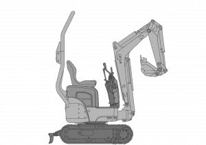
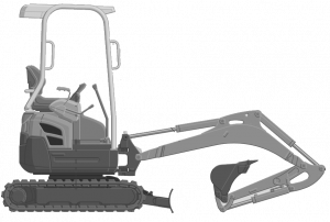
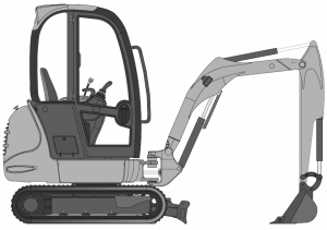
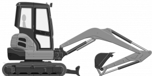
The data for our range of couplers is shown in the table below.
| M0 | M1 | M2 | M3 | |
|---|---|---|---|---|
 |
 |
 |
 |
|
| Min. weight – Max. weight [t] | 0.5 t – 2 t | 2 t – 3.5 t | 3.5 t – 5.5 t | 5.5 t – 7.5 t |
| Max. break out force [kN] | 19 | 28.4 | 38.5 | 56 |
| Typical bucket radius [mm] | 536 | 750 | 900 | 1,000 |
| Max. torque [mkN] | 10 | 21 | 35 | 56 |
| Tooth class [HD] | D5 | D5 | D8 | D10-D15 |
| M4 | M5 | M6 | M7 | |
|---|---|---|---|---|
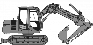 |
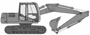 |
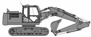 |
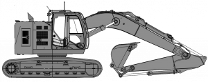 |
|
| Min. weight – Max. weight [t] | 7.5 t – 10 t | 10 t – 15 t | 15 t – 24 t | 24 t to 35 t – 35 t to 45 t |
| Max. break out force [kN] | 73 | 110 | 180 | 249 |
| Typical bucket radius [mm] | 1,200 | 1,300 | 1,600 | 1,900 |
| Max. torque [mkN] | 88 | 143 | 288 | 473 |
| Tooth class [HD] | D15-D20 | D15-D20 | D20- D30-D40 | D40-D55 and D65 |
Teeth classes table
Each tooth has its own specific limits in relation to the break out force applied by the vehicle. It is therefore essential that the tine selected should have sufficient strength to accept the forces imposed, so that the tines do not break or wear prematurely. To help you choose, ACB+ has classified tines as a function of the break out force for which they were designed.
The table below lists the main standard tines, by manufacturer, broken down by tine category. One-piece bolted teeth are shown in bold characters.
| Tooth class | Range of forces at the tooth [kN] | BYG FUTURA Twister | CASE Smartfit | CAT J | CAT K | C-REX | COMBI C / PROCLAWS | ESCO Ultralok |
|---|---|---|---|---|---|---|---|---|
| D5 | 35 to 52.5 | SF4SYL | CAT0 135-9390 | MINI T29 | ||||
| D8 | 52.5 to 62.5 | FT130S | SF5SYL | J200 1U3202 / CAT2 6Y6335 | MIDI T29 | V13SYL | ||
| D10 | 62.5 to 90 | FT170S | SF10SYL | J225 6Y3222 | C0T29 | V17TYL | ||
| D15 | 90 to 122.5 | FT190S | SF15SYL | J250 1U3252 | R10GPE | C1T35 | U20S | |
| D20 | 122.5 to 150 | FT230S | SF20SYL | J300 1U3302 | K80 220-9089 | R14GPE | U25S | |
| D30 | 150 to 215 | FT290S | SF25SYL | J350 1U3352 | K90 220-9099 | R18GPE | U30S | |
| D40 | 215 to 270 | FT330S | SF30SYL | J400 7T3402 | K100 220-9109 | R23GPE | W10GPE | U35S |
| D55 | 270 to 340 | FT390S | J450/J460 | K110 220-9119 | R29GPE | W20GPE | U40S | |
| D65 | 340 to 411 | FT430S FT510S |
J550 | K130 220-9119 | W25GPE | U45S U55S |
||
| D80 | 411 to 540 | U60C |
| Tooth class | Range of forces at the tooth [kN] | FEURST ORCA | FEURST FASTKEY | FEURST SIDEKEY | JCB | KOMATSU K | KOMATSU XS | MTG / KINGMET / STARMET | VOLVO | OTHER |
|---|---|---|---|---|---|---|---|---|---|---|
| D5 | 35 to 52.5 | M15 | MG5L | 5GPC | DE365/17-7 | |||||
| D8 | 52.5 to 62.5 | FKMCE | SDMTLS | MG8L | 8GPC | |||||
| D10 | 62.5 to 90 | 20C | FK1TLR | SD1TLS | 531-03205 | XS04SYL | MG10L | 10GPE | ||
| D15 | 90 to 122.5 | FK2TLR | SD3TLS | XS05SYL | MA15U | 15GPE | ||||
| D20 | 122.5 to 150 | 222TLR | FK3TLR | SD4TLS | K15SYL | XS10SYL | MA20U | 20GPE | ||
| D30 | 150 to 215 | FK4TLR | SD5TLS | K20SYL | MA30U | 30GPE | ||||
| D40 | 215 to 270 | 24TLR | FK5TLR | SD7TLS | K25SYL | MA40U | 40GPE | |||
| D55 | 270 to 340 | 26TLR | FK7TLR | SD8TLS | K30SYL | MA50U | 55GPE | |||
| D65 | 340 to 411 | 28TLR | FK9TLR | SD9TLS | K40SYL | MA60U | 65GPE | |||
| D80 | 411 to 540 | FK11PR |
The general application adopted for this classification is the HD application. Tine performance should be increased by around 20% for an XHD application and reduced by around 20% for a GP application.
Consult us for any extrapolation.
Example for a tine that has to accept a break out force of 85 kN developed by the machine
| FORCE CONSIDERED [kN] | TOOTH CLASS | READING | |
|---|---|---|---|
| HD application | 85 | D10 | 62.5 < 85 < 90 |
| XHD application | 85 x 1.2 = 102 | D15 | 90 < 102 < 122.5 |
| GP application | 85 x 0.8 = 68 | D10 | 62.5 < 68 < 90 |